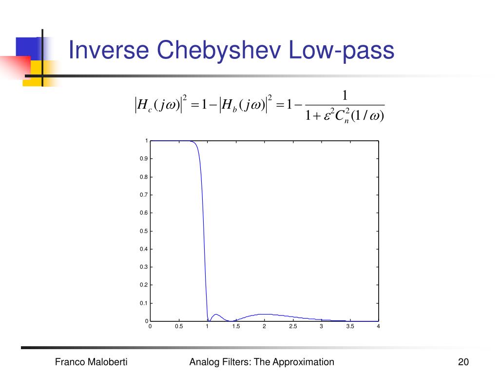

Even so, such passive filters can be useful as anti-alias filters for an ADC provided you can live with the loss of signal. Also, note that it has a 6dB loss due to the resistors. This type of filter is usually used for RF circuits where the resistors would normally be 50W. These resistors do not have to be equal but are a critical part of the filter design. Note that it needs source and terminating resistors. The 3dB point is the same but the rolloff is twice as steep, 12dB per octave. The response is shown below, superimposed over the previous results for comparison. each doubling of frequency) or 20dB per decade (i.e. Filter rolloff well above the 3dB point is 6dB per octave (i.e. The 3dB point is simply 1/(2p RC) so 159kHz with the values shown. The simplest low pass filter is probably a resistor and capacitor: “All pass” sounds like a mistake but is actually a useful circuit for providing a delay which is not frequency dependent (up to a point). Even a digital system needs a filter before the analog to digital converter (ADC) to prevent aliasing, unless one is built into the ADC.įilters can be active or passive, high pass, low pass, all pass or notch. Digital filters are an interesting subject but my interest is more with analog filters. Whole books have been written on filters and filter design, both analog and digital, so a short blog can only scratch the surface. For example, a simple amplifier will have a bandwidth and so above its upper 3dB point it is a low pass filter. Even circuits that you don’t think of as filters are actually filters. It is used in radar to design the display of radar target tracking.Filters are an important part of analog design.It is also used in various communication and control systems.An efficient audio noise reduction tool can be developed using a Butterworth filter. The Butterworth filter is used in the audio processing application.Because of the maximal flat frequency response in the passband, it is used as an anti-aliasing filter in data converter applications.The applications of a Butterworth filter are listed below: The cutoff frequency of this filter is equal to the passband frequency. Cutoff Frequency The cutoff frequency of this filter is not equal to the passbandįrequency. The Chebyshev filter has a narrow transition band compared to the Butterworthįilter. Transition band The Butterworth filter has a wider transition band compared to the Chebyshevįilter. All poles lie on ellipse having major axis R, ξ, minor axis r. Poles All poles lie on a circle having a radius of the cutoff frequency. There is either ripple in passband or stopband. Ripple There is no ripple in passband and stopband of frequency response. The order of the Chebyshev filter is less compared to the Butterworthįilter for the same desired specifications. Butterworth Filter Chebyshev Filter Order of Filter The order of the Butterworth filter is higher than the Chebyshevįilter for the same desired specifications. The difference between the Butterworth filter and Chebyshev filter is as shown in the below table. Type-2 filter is also known as “Inverse Chebyshev filter”. Type-1 Chebyshev filter is commonly used and sometimes it is known as only “Chebyshev filter”. But it consists of ripples in the passband (type-1) or stopband (type-2). The Chebyshev filter has a steeper roll-off than the Butterworth filter. The frequency response of this filter is as shown in below figure.ĭifference Between Butterworth and Chebyshev Filter While designing the second-order Butterworth filter above relation must be satisfy. And if we put this value in equation of quality factor, we can find the value of gain. The value of quality factor is 0.707 for the Butterworth filter. If the value of gain is more than 3, the system will be unstable. And the value of gain should not more than 3. We can say that, the quality factor is only depends on the gain of filter. Now if we put above values in transfer function,įrom above equation, the quality factor Q is equal to, Now, if we consider the value of R 2 is same as R 3 and the value of C 2 is same as C 3. And that is,īy comparing above equations, we can find the equation of cutoff frequency and overall gain for the second-order lowpass Butterworth filter.

Compare this equation with the standard form transfer function for second-order Butterworth filter.


 0 kommentar(er)
